EEPROM INTERFACING WITH AVR
The EEPROM is the permanent storage devices and can be erased and reprogrammed whenever we need. These are the kinds of non-volatile storage chip means when power is removed the content of the memory remains intact. It has no impact of power failure.
Synopsis

The EEPROM (ELECTRICALLY ERASABLE PROGRAMMABLE READ ONLY MEMORY) is a very useful memory which can be used for storing data. The data storing and retrieving from any EEPROM memory is very simple compared to other kind of memories. As the name suggest the memory is electrically programmable and hence the data will be sustained in the memory until it is electrically erased or reprogrammed.

The EEPROM is the permanent storage devices and can be erased and reprogrammed whenever we need. These are the kinds of non-volatile storage chip means when power is removed the content of the memory remains intact. It has no impact of power failure.

The EEPROM is the permanent storage devices and can be erased and reprogrammed whenever we need. These are the kinds of non-volatile storage chip means when power is removed the content of the memory remains intact. It has no impact of power failure.

Description

The 24XXX series serial EEPROMs from the Technology support a bidirectional, 2-wire bus and data transmission protocol. The bus is controlled by the Atmega16 microcontroller (master), which generates the Serial Clock (SCL), controls the bus access and generates the Start and Stop conditions, while the 24XXX serial EEPROM works as slave. The 24XXX serial EEPROMs are I2C™ compatible and have maximum clock frequencies ranging from 100 kHz to 1 MHz

A0-A2 : Address inputs

SDA : Serial Data

SCL : Serial clock input pin

SCL : Serial clock input pin

WP : Write Protect

GND : Ground

VCC : Supply

I2C Communication Protocol

I2C is a bus interface connection incorporated into many devices such as sensors, RTC (Real Time Clocks), and EEPROM. It is also referred to as Two-Wire Serial Interface (TWI) and it is ideal for communication between low-speed devices for a reliable communication over a short distance. The I2C protocol uses only 2 pins, one for clock (SCL) and one for Data (SDA). So, we will first configure and start the I2C protocol with the AVR microcontroller, and then we shall learn how to communicate with the EEPROM.

I2C terminology

Transmitter: This is the device that transmits data to the bus

Receiver: This is the device that receives data from the bus

Master: This is the device that generates clock, starts communication, sends I2C commands and stops communication

Slave: This is the device that listens to the bus and is addressed by the master

Multi-master: I2C can have more than one master and each can send commands

Multi-master: I2C can have more than one master and each can send commands

Arbitration: A process to determine which of the masters on the bus can use it when more masters need to use the bus

Synchronization: A process to synchronize clocks of two or more devices

The configuration of I2C on AVR Atmega16

In order to activate the I2C protocol, In master mode, on Atmega16, you need to configure 3 registers: TWBR, TWSR and TWCR.  We shall use the TWCR register again (at a later stage in this tutorial) to operate the communication.

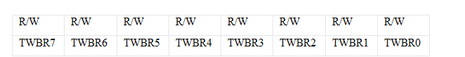
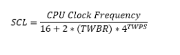
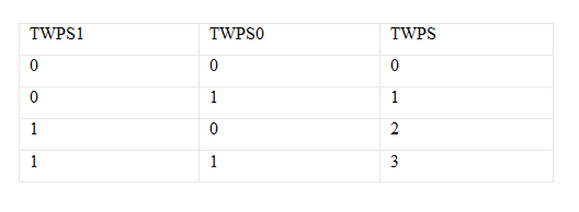
TWBR: TWI Bit Rate Register


This is a 7-bit register whose value is used to determine the bit rate by which data will be exchanged between the two communicating devices. The equation used to calculate this bit rate is as below.


Where (TWBR) is the value in the TWI Bit Rate Register and TWPS is the value of the 2 bits (TWPS0) & (TWPS1) in the TWSR register which will be explained next.

For the purpose of this exercise, we will put the value 0x07 in the TWBR register.

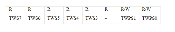
TWSR: TWI Status Register


In this register, we only need to configure bits (TWPS0 & TWPS1) which are used to determine the bit rate as detailed above. The value of TWPS in the above equation is determined as below


In this article example, we shall clear these 2 bits to Zero.

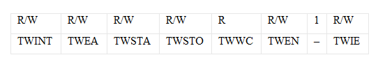
TWCR: TWI Control Register


This 7-bit register is used to control the operation of the TWI.  For now, we only need to set the TWEN bit (bit2), which enables the I2C module and overwrites the I/O functionality of its pins (Port C pins 0 and 1).

I2C Operation

In order to start communicating using I2C you need to go through the steps given below:

>> Taking control of the TWI bus, by sending a start signal to it when it is free.

>> Start TWI Data Transmission

>> Receive TWI Data.

>> Stop transmission and Release the TWI bus.

We shall explain these steps in detail below.

1.Taking control of the TWI bus by sending a start signal to it when it is free

For the MCU to be a master on the TWI bus and take control of it, the MCU senses the bus until it is free, and then sends a Start signal. Having done so the MCU seizes the bus and no other device can send data until the MCU releases the bus, to avoid data collisions. After that, the MCU can start sending data.

In this section, we will write a function for the MCU to be a master on the two-wire serial bus.

>> Set the TWEN bit in the TWCR register to ensure I2C is enabled.

>> Write 1 to the TWINT bit in the TWCR register to clear the interrupt flag. This bit is set to 1 by the hardware when the I2C module finishes its current job and is ready to get more commands from the SW. Also clearing this bit starts the I2C module immediately. So every time we want to start the I2C module, we must ensure clearing this bit first and we shall poll till it becomes 1 again because this indicates the I2C has successfully executed the task. Note: that this bit is never cleared by the MCU Hardware, you must clear it by Software.

>> Write 1 to the TWSTA bit in the TWCR register. Setting this bit makes the MCU send a start signal on the bus when it is free, to declare that MCU is currently controlling the bus and will start transmitting data.

>> Poll the TWINT bit (previously cleared) until it becomes 1. Once this bit is set, it means that the MCU has successfully taken control of the bus as a master.

2. Start TWI Data Transmission

After taking control of the bus, the MCU can send information to it. This is achieved through the steps below

>> Put the data you need to send in the TWI Data Register.

>> Write 1 to the TWEN bit in the TWCR register to ensure I2C is enabled.

>> Write 1 to the TWINT bit in the TWCR register to ensure it is cleared.

>> Poll the TWINT bit (previously cleared) until it becomes 1. Once this bit is set, it means that the transmission is complete.

3. Receive TWI Data

>> Receiving TWI data is even easier than transmitting. You need to follow these steps:

>> Write 1 to the TWEN bit in the TWCR register to ensure I2C is enabled.

>> Write 1 to the TWINT bit in the TWCR register to ensure it is cleared.

>> Poll the TWINT bit until it becomes 1.

>> Read data from the TWDR register.

4. Stop transmission and Release the TWI bus

Once you finish data transmission, you should release the bus so that other devices can use it.

>> Write 1 to the TWEN bit in the TWCR register to ensure I2C is enabled.

>> Write 1 to the TWINT bit in the TWCR register to ensure it is cleared.

>> Write 1 to the TWSTO bit in the TWCR register to send a stop signal and release the bus.

EEPROM Write Data

To write data to the EEPROM you need to do the steps given below with the MCU Software.

>> Take control of the I2C bus.

>> Send the slave address of the EEPROM. Which is constructed as below:

i. The first 4 bits of the address are 1010

ii. The next 3 bits represent the memory page number.

iii. The last bit indicates whether the memory operation will be a read or write. (0 for Writing)


3. Send Start signal again

4. Send the memory address to read from.

5. Receive the data read from the EEPROM.

6. Send stop signal to release the I2C bus.

Applications

>> Low power operation

>> Over 1,000,000 erase/write cycles

>> Up to 8 devices may be connected to same bus

Proteus design for EEPROM interfacing with AVR


Orcad design for EEPROM interfacing with AVR


EEPROM interfacing with AVR

/*  Name     : main.c
 *  Purpose  : Source code for EEPROM interface with ATMEGA16.
 *  Author   : Gemicates
 *  Date     : 2017-09-12
 *  Website  : www.gemicates.org
 *  Revision : None
 */
#ifndef F_CPU
#define F_CPU 8000000UL              // 8 MHz clock speed
#endif

#include<avr/io.h>
#include<util/delay.h>
void init_i2c()
{
TWSR = 0X00;
TWBR = 0X47;
TWCR = (1<<TWEN);
}

unsigned char read_i2c()
{
TWCR = (1<<TWINT)|(1<<TWEN);
while(!(TWCR & (1<<TWINT)));
return TWDR;
}

void write_i2c(unsigned char ch)
{
TWDR = ch;
TWCR = (1<<TWINT)|(1<<TWEN)|(1<<TWEA);
while(!(TWCR&(1<<TWINT)));
}

void start()
{
TWCR = (1<<TWINT)|(1<<TWSTA)|(1<<TWEN);
while((TWCR &(1<<TWINT))==0);
}

void stop()
{
TWCR = (1<<TWINT)|(1<<TWEN)|(1<<TWSTO);
_delay_ms(1);
}

void eeprom_write(char dev_addr,char dev_loc,char dev_data)
{
start();
write_i2c(dev_addr);
write_i2c(dev_loc);
write_i2c(dev_data);
stop();
_delay_ms(10);
}

unsigned char eeprom_read(char dev_addr,char dev_loc)
{
char ch;

start();

write_i2c(dev_addr);
write_i2c(dev_loc);

start();
write_i2c(dev_addr|0x01);
ch = read_i2c();

stop();
return ch;
}

int main()
{
char ch,i;

DDRC =0XFF;
init_i2c();

for(i = 0;i<26;i++)
eeprom_write(0xa0,i,'A'+i);

for(i = 0;i<26;i++)
{
ch = eeprom_read( 0xa0 , i);
eeprom_write(0xa0,i+40,ch);
}
}

Error message here!

Show Error message here!


Forgot your password?

Error message here!

Send OTP

Error message here!

Show Error message here!


Lost your password? Please enter your email address. You will receive a password you Need.

Send Error message here!


Back to log-in

Close